Quite difficult to find one of these "down under"
Yes, this advertisement is packed with detail - the MA-100 needs just a little tender lovin' care and I have tried to give as much information as possible so that a new owner can determine "what they are in for"
Please please read the entire description .... I hate it when someone messages asking "does it work?"
HH ELECTRONIC AND THE MA-100
WOW!
This MA-100 isn't just "another mixer/amp head" but it has pedigree! HH Electronics and their MA-100 oozes Brit audio history ...
Designed and manufactured by HH Electronics, a very well known British company that began in 1968 with their target market being meeting the high demands of the broadcast and professional audio industry. A very respected company with such wonderful creations as the TPA25 and their AMS8/12.
Instead of going on and on about HH, HERE is a link so you read all about them
OR
Watch this 5 minute video spruiking HH, their history and who they have rubbed shoulders with.
Watch intently, at 2:52 you will see the MA-100 on screen and some commentary from the very well spoken English lady!
THE ORIGINAL OWNER AND OH MY! THE PLACES THIS HEAD HAS BEEN ...
Late 70's ~ early 1980's and UK punk was the original owners scene, actually sort of anti punk or some might say anti everything! There was a UK band called The Crass, sort of an intelligent punk band with thoughtful lyrics ... more than just God save the Queen, the facist regime" sort of stuff.
Here is one of The Crass songs
The original owner of this head was into the punk/anti-establishment music scene, and idolised the likes of The Crass. He put together a group of guys and they played basement gigs all over the place, just about anywhere that would let them. This M-100 was his "Greenie" amp, his "girl". Unfortunately he became very very ill and the rest is history ...
So this isn't "just" a MA-100, it has a history and I now want someone to look after it and use it once again.
My professional background is the audio industry, the technical side of things and yes we used to service gear but these days I am not the person I used to be (bung eyes, bung ears ... damn, I can barely walk at times!) so I am giving this amp a very thorough looking over (the brain still works) but I will not service it myself.
How do I know it needs a service? After almost 40 years just sitting around EVERYONE needs a service! There is no way anyone can reasonably expect this gear to be 100% after such a long period of rest.
So enough of the **** and on with the real information
HH ELECTRONIC - PA MIXER-AMP HEAD
Model: MA-100
Designed & made in UK
Serial # 16949
240V AC power input ONLY using a standard IEC C13 socket - this is not a multi-voltage mixer/amplifier
Circa mid to late 1970's
MIXER: 5 independent unbalanced input channels
Each channel has:
Two input jacks, Hi Z @ 35mV sensitivity and Lo Z @ 4mV
Separate Bass & Treble rotary controls on each channel
Reverb switch ON-OFF
Additionally there is a Master Volume rotary control, Master Presence rotary control & Master Reverb rotary control
Well "considered" mixer section, particularly for vocalists
Additional facilities:
Auxiliary input, used to connect two MA-100's together which provides extra input channels
Echo SEND and RETURN
Reverb foot pedal ON-OFF jack
Slave output (intended to be used with the S.130 Slave amp)
POWER AMPLIFIER:
Easily capable of providing 100W output RMS into 4 Ohm load speaker bins
Output is comfortable with loads between 4 Ohm & 15 Ohms, higher impedances though mean less output - pretty standard that most bins will be 4 Ohm
SPECIAL FEATURE:
Cool (and functional in a dark playing environment) Green glowing front panel (see the photograph of THIS mixer/amp head with the power on)
DIMENSIONS: 640mm Length x 310mm Deep x 110mm High
WEIGHT: 10Kg ("just" manageable if being carried around)
COSMETIC CONDITION:
This MA-100 has been around, years ago. Since the 1990's it has sat in our audio production workshop "backroom" waiting for one of the techs to take a look - too busy so I thought it never happened but read my notes below, someone has had a "quick look" inside sometime in the past.
The last few weeks is the first time I have had an opportunity to give it a "looking over" .... here is what I have found
Side Black polycarbonate handles are NOT damaged (NO cracks or missing sections!) although some light scuff marks.
Large chrome side nuts are in great shape although a couple have slight discolouration (no big deal)
Vinyl covered plywood top and bottom covers are in very good condition with no damage to either - BUT to my dismay, MOST top & bottom panel screws are missing!
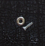
I think one of the techie's may have taken a look inside and then lost the screws/washers ... fortunately these are very ordinary and I am positive a place like Bunnings will have exactly what is needed (see the photograph below of the screw and washer) I only found 3x sets of these (you need 4x sets for each panel top/bottom) so I have fitted them to the base panel, once I had taken a good look inside the MA-100.

Front panel fascia is in great shape, all decals are easy to read
Front panel knobs are a different story! After years of use (back in the late 70's ~ 1980's) the finish on the PLASTIC knobs has worn quite badly.
They do not look pretty and spoil the front visual aspect of the MA-100 quite frankly. Why bother about the look? This mixer-amp head is not only about the sound but also "the look" - those nice bright Red jack sockets, the strangely haunting Green front panel glow and then there is the knobs - what a let down!
Either replace them with nice new knobs to suit or refurbish the existing knobs. NONE are broken or have cracks, these are "push on-pull off" D style shafts - no screws. The larger knobs all have a felt pad underneath, none are missing. To assist with replacement knobs (some decent solid metal knobs would be good but could be hard to find at the right price!) I have included some measured dimensions below ...
LARGE KNOB: (7) 18.85mm diameter x 16.50mm height, Black side/top marker line and a "saucer" shaped top end piece (for the finger) with a D female socket for a 1/4" pot shaft. This fitting also has a metal clamp around the plastic D clamp to provide strength. Felt washer fits into the base, 13.6mm diameter - none of these felt washers are missing.
SMALLER KNOB: (11) 12.65mm diameter x 15.75mm height, Black side/top marker line and a "saucer" shaped top end piece (for the finger) with D female socket for the 1/4" pot shaft. This is a metal clamp around the plastic D clamp to provide strength. No felt washer is used on these smaller knobs.
Rear panel is also clean and undamaged in any way - again, all decals are clear and easy to read
LOOKING INSIDE, OBSERVATIONS AND A SIMPLE TEST!
Easy to get inside although I wonder about some of the service accessibility - I see rivets used in places which could make life interesting for the service person!
OMG! All interconnecting internal wiring is laced, so time consuming for manufacture and see this takes me back to the "old days" in telecommunications - put together with care!
Nicely laid out, rear panel has the output transistors on one side and driver PCB the other. This MA-100 has the driver board marked as AS00014 2 - semi's on this board include 2SB536 (NEC) and 2SD381 transistors, SFC 2741DC 8 pin DIL Op Amp and the output trannies are 2x 2N3773 behind that rear shield. I had a quick look around online and these do not appear to be difficult to source and not expensive! NO component stress has been observed, passives (nice Philips Blue electro's) or semi's. No signs of PCB "burning" or component meltdown!
SAFETY HINT: While the IEC socket has heatshrink applied to the wiring, the wiring around the fuse holder have NO heatshrink. To prevent accidental electric shock when inside, it would be a good idea to "shrink up" that fuse holder at the very least - fitting a "boot" to the IEC socket wouldn't go amiss either.
Next we move onto the centre panel (pressed steel U channel), this is where the toroidal AC transformer, 2x filter capacitors and the nice old analog reverberation double spring line sits.
First thing I noticed was that the filter caps are SHOT, kaput, gone to heaven! At some stage they have leaked electrolyte down onto the Driver board but done NO DAMAGE to that board, one capacitor is bulging - there is NO WAY you should power up the MA-100 in this condition! This sort of thing happens to the best of us oldies, electro caps especially can do this sort of thing.
The existing bad capacitors are nothing special, 4700uF 50V solder terminals in a 35mm clamp. The capacitor measures 35mm diameter x 50mm height. Who made the caps? (I hear you asking) ERIE - Nup, me neither - never heard of them! Must have long gone in the mists of time. Actually hunting around (curiousity) I suspect these are Japanese from Chemi-con - that would fit in with the Japanese driver transistors.
From my workshop spares I DO have electro's that will be perfect for the repair (nudge nudge wink wink, say no more!) look HERE at the beautiful EPCOS capacitors and they have a slightly higher voltage rating! I have the 35mm clamps too!
The repair would be straight forward EXCEPT that HH Electronic have riveted the clamps to the U channel - Urghhh! Why oh why make life so difficult? So those clamps need to removed from the channel and replaced with new clamps - the side tightening clamp is also a rivet.
AT THIS POINT I WANTED TO SEE IF THE TRANSFORMER IS FINE (at the very least)
I have disconnected the output spade terminals of the 25A bridge rectifier block. No power will be supplied to the rest of the mixer/amplifier - particularly those electro's!
Plugged in my 240V AC IEC lead and flicked the ON-OFF rocker switch. Although it looks like it would have a neon light inside, it doesn't seem to have and I checked around online at other MA-100's and cannot find ONE that has the switch lit up.
The lovely glow is very cool, if you are in the dark that is - it is not "in your face" but a nice subdued Green glow around the control knobs on the front panel. This is powered directly from the AC transformer.
I measured the UNFILTERED DC output at the bridge rectifier, I have 60V here - which is something like I would expect, although I must say that using 50V working ERIE electro's previously must have been running them pretty "borderline" - this could be the reason they blew their brains out!
Looking good, the AC transformer is fine (also the front panel illumination and the bridge rectifier) - next step for someone would be to change those electrolytic filter caps and go from there ...
Moving right along, the spring line (double spring with magnetic heads at each end) is in great shape, no damage to the magnetic heads nor the spring lines themselves, including the four corner support springs for the whole delay line assembly.These spring delay assemblies sit "hanging it all out", floating if you like, so the four corner springs are vital to correct operation without strange noises if it is being moved around. Fun little devices these spring lines, days of old analog delay lines - I once saw one that the ABC Workshops had made, 2 metres Long...Long...Long! Well before the days of digital delays and manipulation of audio.
Lastly, there is the front panel (on the inside) to take a look at.
I was not about to totally dismantle the front section to look very closely at the large/long PCB so these are observations as best I can make. The board is loaded with nice polycarbonate caps - nice! I see some i.c's in there but cannot read what type they are. Everything "looks" honky dory, no-one has been messing around here. I tried to see if I could figure out who made the Red jacks but I couldn't find any markings - these are totally isolated jack sockets. The pots used for the front panel controls look very "standard" with no special fittings and a plastic D shaped shaft. It is difficult to read the info off the back of the pots but at least a couple are 22K (might be a challenge to find if you needed one) and a part number 90664 - no manufacturers name. Hopefully these will only need a good squirt of cleaner to have them noise free, that is if they are noisy.
I then noticed that the Channel 5 reverb ON-OFF switch isn't quite right. Each of these switches has a bolt from the aluminium frame holding the switch in place. All the other reverb ON-OFF switches are fine (and work fine too PUSH ON (lock) PUSH OFF (release)) but Channel 5 there is NO bolt so the switch action works fine but the switch is not being held in place properly - the new owner will need to fit a new bolt to secure this switch. The bolt looks to be nothing special at all.
ANOTHER SAFETY HINT:
I looked at the rear of the ON-OFF rocker switch (SPDT) and there is NO heatshrink or other protection to avoid accidental electric shock when servicing with the power ON. While this switch is quite recessed into the front panel, the danger of electric shock still exists and it would be wise to fit insulation (heatshrink or some type of boot) to the rear of this switch for safety sake.
SUMMARY:
Original as - no work has been undertaken on the boards and nothing looks to have been replaced in the past.
"Greenie" is a classic 1970's mixer/amplifier and I have no doubt she will fire back into life once those filter caps are replaced, history in your hands!
Yes, this is a very long and detailed description but that is the way I am - technical and full of detail, spent quite a bit of time on this now take a think about taking her to your house/workshop!
PLEASE KEEP IN MIND THAT THIS PRICE INCLUDES FREE SHIPPING ANYWHERE AROUND AUSTRALIA


