Way back in the dim dark past, a shared access radio telephone service was offered to commercial operators by Telecom.
In the 1980's, setting up your own radio communications system was expensive, but Telecom was able to offer "shared" radio communication services (although still quite expensive) to reduce the cost to businesses of such systems and provide them with a reliable radio communications system.
Telecom provided the radio communications equipment, located at their telephone exchanges.
Leased telephone lines would connect the subscriber(s) back to the exchange and then to their radio communications systems. It operated like a fixed line "party" system, where a number of subscribers could share the same radio channels.
Each leased line was terminated with control equipment, such as that which I am offering here.
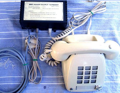
Subscribers could access the radio communication channel via a leased 2 wire line to their premises and at the end of the telephone line would be equipment such as this RC-7C, usually in the office.
This subscriber equipment has no RF components, it is for access and control of the radio communications only.
Early systems had very basic control and used techniques such as line reversal to make the subscribers equipment "come alive" when they were being called (line reversal simply made the loudspeaker become enabled)
Later versions were more sophisticated - the RC-7C is one of the later incarnations and uses CTCSS encoding/decoding to ensure the correct subscriber was connecting with the correct mobile stations.
Seems archaic but it must be kept in mind that any type of mobile telephone system (GSM/UTMS/CDMA) was not yet commercially developed.
All communication was simplex (communication can only be in one direction at a time), "talk then listen, talk then listen"
Compared to current digital radio systems, this equipment is "stone-age" and would be of no practical use except if the CTCSS IC is used in another "project" but it is far more likely this equipment will only of nostalgic/museum piece/talking point value.
That said, there is still potential to setup this equipment for use with UHF CB or VHF/UHF Amateur radio channels as they still use CTCSS sub tone signalling.
TELECOM Radiotelephone Control Unit
Model RC-7C
Manufacturer: AWA Australia (when Australia had a thriving electronics industry!)
Original power supply (40V @ 20mA & 12V AC @ 500mA)
Cream coloured case and handset
Ready to "go" with a special 604 plug fitted
TECHNICAL INFORMATION:
The equipment comprises two primary components, one is the power supply and the other is the subscriber equipment.
The power supply is a linear 240V input with 40V & 12V DC outputs to power the "telephone"
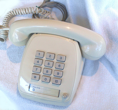
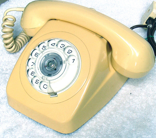
The telephone case uses an 807 casing which has been extensively modified.
The push-button dial is gone and in its place is a small loudspeaker. A volume control has been fitted and a miniature toggle switch.
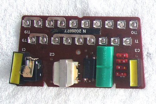
Inside the subscriber equipment, there are two boards.
The original 807 board has been removed and another is in its place, marked only as 05 '88A & 82296-1-02 (PCB side)
This is the voice signal board, with links to setup the telephone as a Radiotelephone Control Unit or as an Extension Phone off an existing RC system. It is currently linked as the former.
Chips on this single sided board are 1x TBA820 (audio amp Class B), 1x LM339, 1x LM324. There are two pots fitted, one is to control the line CTCSS audio level in and the other, line CTCSS audio level out.
The second board is all about the CTCSS signaling and is based on the COM-SPEC IC-107 CTCSS encoder/decoder chip. ALL chips on this board are socketed, so they are easy to remove. Two other chips are on this board, a TL062 op amp and LM324.
The IC-107 has an associated 5 way DIP switch, allowing up to 32 different frequencies to be selected. It is currently set for 100.9Hz
I have the full specifications and programming info for this chip, it is easy to setup other CTCSS frequencies.
The only other item of note is the line plug, a type 604 but this has a keyed lug which means it will not fit into a standard Telecom socket (unless you grind down the lug!) also the wiring is not the same as a standard 2 wire telephone.
Pin 6 = Red
Pin 4 = Blue
Pin 3 = Yellow
TESTING:
I powered up the equipment, all is good. A low level "white noise" hiss from the speaker. I then sent audio down the "line" and can hear that audio for about 0.5 second and then it mutes - I suspect the equipment is listening for the CTCSS tone and as there is none, it goes into mute. The level control works fine.
The miniature toggle switch seems to mute the loudspeaker when in the "down" position, possibly enabling CTCSS decoding so it would remain quiet until the correct tone was received.
The handset has a small PTT fitted, when pushed I have "side tone" so all is good here too.
That is about the extent of testing that I can make without any equipment to send this equipment any CTCSS tones or "listen" to them via the line.
