SUSTAINABILITY:
To many this item is just a used lump of metal but I am big on reusing or repurposing old electronic components and hardware, particularly from the point of view of sustainability.
Sustainability is far more than NOT burying waste material back into the earth but consciously recognising the energy expended to create the item through it's various "stages" in life, beginning with the raw materials being extracted from the earth, processed, finished and then fitted into equipment - every single step used energy which is referred to as embodied energy.
Coming up with an Ee value for EVERYTHING us humans create is an attempt to take into account the energy used for extracting and processing of the raw materials, manufacturing of the component, distribution of the component(s) and final assembly of the component. In fact the measurement of Ee can become extremely complicated and technical, many tertiary institutions are involved in this specialised field of science.
The sole purpose of establishing Ee values is to raise awareness of the extraordinary energy consumed in the creation of various items - it may give you cause to think twice before wasting all that energy and burying it in the ground, with the possible side-effects of poisoning the environment due to leeching.
HERE is a page I have created which gives some tables and more detailed information about specific Ee values for different materials plus a link which you can use as a starting point to investigate Ee for yourself.
HISTORY:
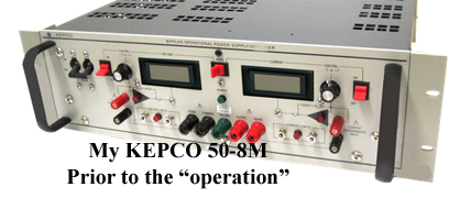
This component has been pulled from a very nice (fully functioning) KEPCO BOP 50-8M!
Why "part out" the KEPCO? I have decided to make this equipment an "organ donor" because I have had it advertised elsewhere as a fully functional unit but no interest, too "high brow" I guess.
Additionally it is VERY HEAVY (this is a FULL rack size unit, approaching 40Kg when it was packed) and I noticed light damage to the steel casing as well (scrape marks due to moving it around over the years).
Originally we acquired this equipment from an international R & D laboratory and used it ourselves for various test and research tasks, although the BOP range of Bi-polar power supplies can undertake many other tasks.
In brief, the KEPCO BOP 50-8M is a Bi-polar power supply providing 0-50V dual supplies at up to 8A current each.
But to be more specific it is much more than a Bi-polar power supply, the unit contains two high speed, high power Op amps and NO capacitors on the output (which can effect the frequency response/speed). The Op amps can operate up to 24Khz (resistive loads) with Ultra low noise, Ultra low ripple and they are MIL spec compliant.
The power Op amps are four quadrant, bi-polar operation with full control of the voltage and current on each channel via the front panel controls OR remote control/programming.
This KEPCO BOP 50-8M is not a "spring chicken", date of manufacture was in the late 1990's - not used very often but when it was called upon, it never missed a beat.

KEPCO designs and manufactures some wonderful professional laboratory and industrial power test equipment, take a look HERE for their latest offerings
The company began around the mid 1940's in Queens, New York along with two other very well known power supply design/manufacturing companies Sorenson and Lambda. Of the three companies, only KEPCO remains in Queens and remains an independent company.
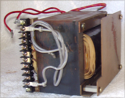
So, that is the background of this component and now let's get down to describe the component or module I have carefully extracted from the equipment.
KEPCO - Heatsink Assembly
Designed & made in USA
This has to be one of the best engineered, laid out and capable heatsink assemblies I have seen in recent times. Carefully extracted from the KEPCO BOP 50-8M and I continued to be amazed while the extraction took place. A lot of thought and engineering skills has gone into this design.
Materials used: Metal alloy fins and I am 99% sure now that the main heatsink "plates" that the transistors mount directly onto are Brass. The metal is too heavy for Aluminium and not the right colour for Copper. When I look down into the threaded holes in this plate I can see that distinctive Yellow/Orange of Brass. That's my best guess at this time!
Compact design and yet it is looking after the cooling of 12x TO-3 power transistors (assisted by forced air)
The KEPCO BOP 50-8M has two of these fitted (see the original photograph before the "operation") each providing up to 50V @ 8A - the transistors are the output stages for the positive and negative supplies.
Very easy to repurpose and there is no need to drill holes or find unique hardware to use it.
I do not have any thermal data for this heatsink but it was "keeping cool" 6x 2N3773's (Find them HERE) AND 6x 119-0128's (Special numbering, GENUINE Motorola 2N6609's - see the advertisement for those HERE (NOT YET A "LIVE LINK" ON MY WEBSITE BUT WILL BE SHORTLY)
Includes Brass transistor mounting bolts (the heatsink has threaded holes), TO-3 insulating bushes and even nylon stand-off feet with screws for secure mounting.
Heatsink assembly weight: 1.4Kg
It is extremely unlikely that anyone is going to need this heatsink assembly for their KEPCO equipment so the name of the game is re-purposing and what follows is a lot of information to allow judgement to be made as to the suitability of this heatsink assembly for your "special project"
MEASUREMENTS:
Complete "block": 156mm wide x 105mm height x 84mm depth
Transistor mounting "real estate" area: 67mm wide x 105mm x 5mm thick Brass EACH SIDE of the "block"
Fins: 40mm x 80mm x 77mm height EACH SIDE of the "block"
Fin count: 21 on one side and 29 the other side. The side with lesser fins has greater spacing between the fins and the material (metal alloy of some sort) is thicker than the other side)
Mounting feet: 4x on the base, 100mm apart on the same side and 65mm apart between the sides.
Engineering build notes:
The two side fin assemblies with the two thick sheets of Brass between them are fixed in position and cannot be changed (look to be braised together) There is no way that this will "come apart" or can actually be separated.
Each Brass plate for the transistors (and a thermal cut out switch) is pre-drilled for 6x TO-3 case transistors. Three of the transistors have their case directly in contact with the metal plate and three transistors have extra large holes for the fitting of the insulating bushes (supplied) - those transistors of course used silicon washers (since discarded). As there are two plates for the transistors, the whole heatsink assembly is looking after the cooling needs of 12x TO-3 transistors. So to make this clear, each side of the heatsink is populated by 3x TO-3's where the case is directly in contact with the plate and the other 3x TO-3's are intended to be mounted INSULATED from the plate.
In the original design, KEPCO created an ingenious PCB based connection system with the transistor pins fitting into sockets on the board. This PCB (2 of them actually) sat inside the heatsink, BETWEEN the two plates and the various external connections were presented at a topside edge connector. This makes servicing a "snap" but is pretty useless for a custom heatsink project so the PCB/edge connectors etc have all been discarded.
Unless someone went to the trouble of re-creating a new PCB with built in transistor pin sockets, the transistors will need to be hard wired on flying leads. There is plenty of space between the two plates, 33mm width.
At the base of the heatsink assembly are four metal feet which are bolted onto the heatsink frame and into which are inserted nylon plugs for a screw, this mounting arrangement is very sturdy. If this type of mounting wasn't desired, those feet can be removed easily.
COSMETIC CONDITION:
USED
Clean
All silicon grease has been removed
Very good condition
NO fin or structural damage
12x shorter Brass bolts are already fitted on the heatsink (so they don't get lost), a further 12x longer Brass bolts are in a plastic pack (they are used with the transistor insulating bushes)
12x White plastic transistor insulating bushes are supplied (also in a sealed pack) - in perfect condition.
2x Chrome finished bolts are fitted already on the heatsink (again to prevent them getting lost), these were used for the thermal switch originally.
All mounting feet metalwork, nylon plugs and metal screws are supplied.
Basically all you need to do when using this heatsink assembly is have some silicon TO-3 insulating washers on hand, plenty of Silicon grease and a lot of hardwiring to the transistors, allowing enough length in the wiring to make the transistor connections and then fit the transistors into position. It is possible to mount your own custom PCB board on top of the assembly (horizontally) as many transistor connections are likely to be common anyway.
While this assembly certainly will help keep your transistors cool, some forced air wouldn't go astray either - depending upon the power dissipation to be expected. I have some VERY GOOD fans from Germany HERE
Currently being "written up" please be patient, so many things to advertise and so little time!


