HISTORY:
My experiences with Vifa began back in the late 1980's, some DIY high quality loudspeaker systems were being offered by an electronics retailer and apparently the design of the system was by Scan Audio, a very respected audio engineering company in Australia.
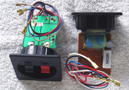
The loudspeaker system was two way, front porting and based on Vifa loudspeaker components. This is the original crossover network used in the system, I am not sure (it has been many years!) but I think the loudspeaker system was labelled the SA-100 and it had VIFA front badges.
I have used that system for years, almost constantly, for listening to all the music I advertise when I am not checking out other loudspeaker systems.
Why am I parting out my tried and trusted audio friend? We have had rain, lots and lots of it, and I discovered during one storm that water had run down the wall INSIDE the house and worked its way over to the floor standing speakers - OMG! I dried them off (it wasn't deep water but enough to make the base of the speaker cabinets damp) and hoped for the best. Well, over time the cabinet particle board has expanded and is now crumbling at the base. It looked terrible and I decided it was time to change loudspeaker systems after all these years so now I am running some Aaron's (Australian) and Dali's (Denmark) and the parts from my Vifa loudspeaker system are seeking new homes!
Oh, and yes, there is NOTHING wrong with this crossover network ... see full details below
Great for your customised 2 way loudspeaker system OR use it as a component 'farm' for your own crossover design
UNBRANDED - Crossover Network (1)
Although used with my old VIFA system, this crossover is not VIFA product, I suspect it was designed by Scan Audio who had a lot of input re the loudspeaker system design.
Model: unknown (particle board base has 100 stamped onto it)
Two way - for splitting the amplifier output frequencies to a driver/woofer (see HERE) and the tweeter (see HERE)
Nominal impedance 8 Ohms at the speaker terminals
Power handling capability: 100W RMS
Complete with all leads - ready to use
Leads (polarised markings) are:
Blue: Goes to the rear speaker terminals
Brown: Goes to the tweeter
Black: Goes to the driver/woofer
Point to point wiring using a tag strip
Base used is a particle board 10mm thick and dimensions 90mm x 220mm
Base has 4x holes for securing inside the loudspeaker cabinet (screws supplied)
Passive components used:
Inductor 1 (Orange former): Ferrite core (removeable) measuring 1.18mH with core, 0.28mH air core only
Inductor 2: 0.21mH air core
1x COSONIC 10uF 50V non-polarised electro
1x MITSUBISHI (?) I can only see what appears to be the Mitsubishi Electric logo stamped on the body PLUS the text :FOR AUDIO CROSSOVERS 4.7uF 50V and it appears to be non-polarised
1x Poly capacitor but it is sitting under the Mitsubishi electro and unable to be read (glued together) - this capacitor is wired in parallel with the Mitsubishi
4x 5W Wirewound resistors, being 2R2, 2x 6R8 and a 15R
NOTE: Inductor 1 with the ferrite core. It does have a "resin cap" but this is quite easy to remove and the ferrite tubular insert is just sitting inside. You can either reposition the ferrite or remove it altogether to create new inductance values - no need to touch the windings.
Both inductors (and in fact all wiring) is heavy gauge, I would say this crossover is VERY conservatively rated at 100W RMS handling although you would still need to consider the power dissipation in those wirewound resistors.
Obviously I tested the inductors/measured their values (so you can work out your own LC requirements if custom designing your own network) and also both capacitors, which were "spot on" albeit a bit off with the parallel pair of capacitors, which is to be expected.


