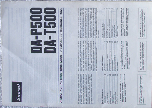
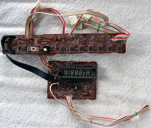
This Sansui DA-T500 stereo system developed an issue with the cassette player and the it was deemed uneconomical to repair, so the useful parts of the system have now been parted out with a view to repair but more likely, re-purposing.
The Sansui DA-T500 is now an "organ donor", sacrificed so that the embedded energy used in the creation of these parts is not wasted.
I am very "big" on sustainability, re-using or re-purposing equipment (no matter how trivial or old it may be) because a LOT of EE (Embodied Energy) was used to create this module and to throw something like this away, poison our landfill etc is just so irresponsible and such a waste of expended energy. Everything we humans have created required energy (and raw materials) for it's creation and often that amount of energy (EE value) is surprisingly high. So after using those raw materials and expending considerable energy to create an item, we then throw it away! Such terrible wastage.
Anyway, here are the complete details of this power amplifier
Hint: great to use as the basis of a quick, custom made. low power 2 channel audio amplifier
Sansui DA-T500 Stereo System (SPARE PART)
Parts offered (as pictured):
Complete audio power output module
Power output 25W + 25W RMS
Part # F.4333
Complete PCB with all components fitted including the flying lead for the headphone board, plus that board.
Module weight: 450g
Dimensions: 200mm wide x 110mm length x 95mm height (to the spindle top)
4x mounting holes on the rear heatshink make for easy mounting
Molex style connectors used for AC power and audio signals
DETAIL:
Simple linear power supply is designed for 27-0-27V AC input, full wave rectified and electro's on each supply rail (positive and negative)
All the hard work is done by a thick film hybrid integrated circuit, a STK4141II, in fact there are no other semi's on this PCB except the power supply section.
This device is capable of up to 25W RMS per channel (Sansui appears to have used poetic licence and is quoting 30W per channel), a bit optimistic based on the specifications for the power amplifier hybrid chip.
THD is quoted as 0.4% @ 1W but no figures in the specs for higher level outputs
There is no indication of the drive voltage required to achieve maximum power output but it would be safe to assume this figure to be between 1V ~ 2V from the preamplifier output
Frequency range: 20Hz ~ 50KHz
Output noise maximum 1.2mV (+/-31 DC supply rail)
Designed for a maximum case temperature of 125C - this means the heatshink sized can be reduced
The heatsink used measures 108mm x 95mm x 55mm finned aluminum (bare not painted)
Recommended to have a load impedance of 8 Ohm but the Sansui DA-T500 rear panel suggests this module can handle 4 ~ 16 Ohms
Built in mute circuit (pin 6)
COSMETIC CONDITION:
PCB is undamaged
All components are original and clean
TESTING:
Prior to this DA-T500 becoming my "sacrificial lamb" I tested the complete system, particularly the audio outputs on each channel.
There are NO issues at all, nice clean audio on either channel.
Heatsink barely became warm even at higher powers.
Low quiescent current when idle, around 30mA
NOTE:
The PCB is only marked with numbers at each molex connector. The pin designations are:
37 - AC 27V in
38 - CT from AC transformer secondary
39 - AC 27 in
40, 41, 42 normally also had AC supplied from the main transformer but this AC is simply rerouted back over to other boards so these can be ignored for a "custom" power amplifer
20,21,22,23,24 & 25 (24 is audio "hot") are all inputs signals for ONE channel - this connector brings in the signals (including mute) from the control amplifier boards (these are sitting between the preamplifier and power amplifer and provide tone/balance audio control
26,27,28,29 & 30 (30 is audio "hot") are all input signals for ONE channel - this connector brings in the signals (including mute) from the control amplifier boards (these are sitting between the preamplifier and power amplifer and provide tone/balance audio control
ATTENTION: One channel molex connector is 6 pin, the other channel connector is 5 pin
Since removal, I have now carefully packed and sealed this assembly in sealed plastic to keep out dust.


