HISTORY:
Sustainability is the name of the game! Anything that can be reused or repurposed creates Ee savings and reduces the poisoning our environment when items are buried in the earth at the local tip needlessly.
Never heard of Ee? It is a concept that creates a measurement of ALL things (not just electronics) that humans have made and the energy used in obtaining the raw material, processing the materials right through to a finished product and even should include the shipping of the item to the distributors/retailers.
If you would like to know more about Ee values, please take a look HERE
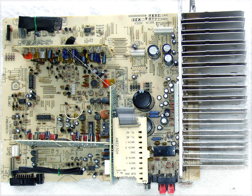
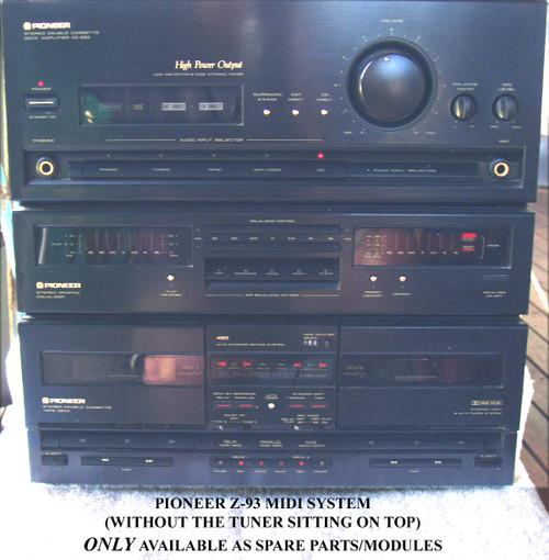
So who may want just the main board assembly (with three daughter boards) for the PIONEER Z-93?
Sometimes catastrophes happen! I saw a main board that had both power supply filter capacitors "self destruct" and in doing so, caused a lot of PCB damage in the surrounding area - it was easier to fit a replacement main board than try and patch up the old board.
I also used to keep one of these main boards "on hand" as a source of components for other Z93's - very handy
This is not an easy board to disconnect and "lift out" as there are quite a number of interconnect points although most (but not all) are the WHITE connectors (ribbon cable is easily removeable) but there are a couple of solder type connectors as well.
There is a trick to doing the ribbon cable disconnect/connect procedure ...most of the ribbon interconnect cables are connected on the Main board with WHITE connectors (this is very important - the Grey/Connectors are NOT push fit types)
The white connectors work like this ... it can be seen that they "clamp" together holding the ribbon cable wires in the process BUT do not try to lift the top section of the connector upwards to release the ribbon cable - it will not work and you risk destroying the connector! It is actually easy to remove the cable (but not so intuitive) - PUSH DOWN on each end at the same time and while this downward pressure is applied, lift up and out the ribbon cable - it will release easily! You really need three hands but a "widely spread" pair of small pliers can help. Use the pliers to apply the light downwards pressure evenly to the connector top section (at each end) and use your other hand to lift up the ribbon cable out of the connector spring contacts. Bingo! you have freed the ribbon cable - insertion is the reverse process.
This main board also has three "daughter boards" soldered to the main board, mounted vertically ... more details of them are below
PIONEER - MIDI Stereo System Component
COMPONENT: Main Z93 System Board Plus
PART # : AWZ2630 (Main Board) AWK1179, AWG1034 & AWK1178
Supplied with the 3x soldered interconnection ribbon cables intact, the white push connectors having had their ribbon cables released
NO cabling has been cut.
COSMETIC CONDITION:
Very nice condition!
CLEAN
NO damage to the PCB board or components. This MUST be handled carefully as the PCB is "one end heavy" due to the large heatsink and audio output components, always support the PCB when moving it around.
NO damage to the ribbon cables at all
OBSERVATIONS:
Known to be fully functional as it was removed from our Z93 with the failed twin cassette decks, ALL other functions were working perfectly.
Now what are those active devices?
In a nutshell, many!
Those of most likely significance are:
SONY CX20187 IC (Dolby B/C Noise Reduction)
2x LA3607 IC (7 band graphic equaliser)
LC7522 IC (electronic volume control for the 7 band equaliser providing 2dB steps)
TA7291S IC (linear bridge driver)
STK4192-2GP (hybrid audio amplifier 50W + 50W minimum)
The 4x TO220 devices next to the power amplifier module are standard 3 terminal regulators for the 12V & 5V rails
The remaining DIL devices on the main board are "garden variety" 4066 switches, a 74LS device and a 4558 Dual OP amp
I didn't see the need to look at all the transistors but looking at the schematics, PIONEER have used a lot of the "digital transistors" with the built in bias resistors.
I cannot see any signs of any component stress and the 2x ELNA filter capacitors have no bulging or leakage points.
Since looking the board over, I have now placed it onto a very stiff cardboard base and sealed it within plastic to protect it from the environment and movement.


